ESPHome Auto-Restart Script
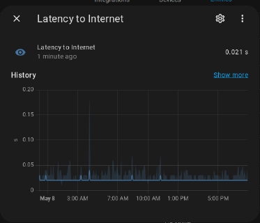
Introduction Running various services at home can be a great convenience, but it’s incredibly frustrating when the network goes down and you’re not there to restart everything. I’ve …
As part of a larger project, I wanted a way to capture the audio signal from our HiFi and sample it with an ESP32 Microcontroller. Our HiFi has a handy tape-dubbing output which I’m unlikely to ever use for that purpose, but it’s ideal for connecting the ESP to.
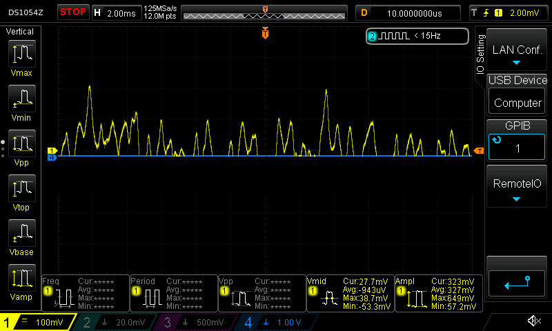
Here’s a sample of one channel of the audio signal:
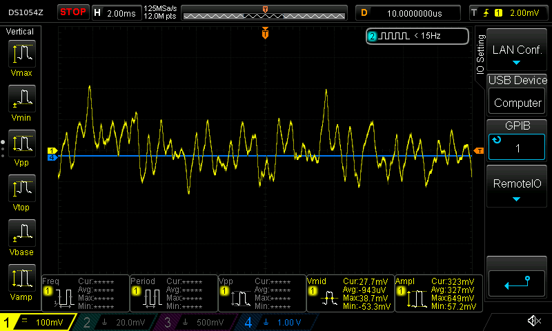
My first thought was that I could run that straight into the Analog-to-Digital converter on the microcontroller, and while I’d lose the lower half of the waveform, that wouldn’t matter too much since, for this project, I was primarily concerned with the frequency. If I had something like this, I could do a pretty good job approximating the complete waveform.
However, that doesn’t work when the waveform has more bass. Consider this example:
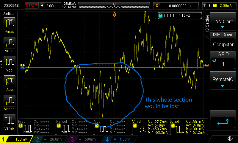
Instead it’s clear that i’m going to need an analog circuit to accomplish two things:
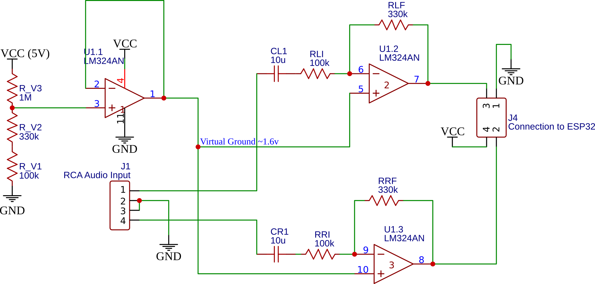
I settled on the following design:
I proofed this concept on a breadboard and it seemed to work pretty well. Here’s the original waveform (yellow) with the amplified waveform (torquoise). Note that the waveforms are on different scales.
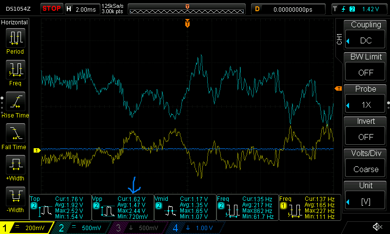
You can see that the Peak-To-Peak voltage is maxing out at 2.44V in this little sample - which is about perfect for our needs.
Breadboards are handy for simple tests, but the wire connections aren’t very good and you get lots of weird capacitance issues which made the circuit unreliable. Making a proper PCB for this made sense, but this as a whole new experience for me.
I entered my schematic on EasyEDA as their tools should be able to easily convert that to a PCB.
They have a great user interface that lets you place components in both the schematic and on a PCB at the same time. When I search for the LM324 Quad-Op-Amp I can select it in a whole array of packages and configurations - I went for a simple DIP package since that’s within my soldering capability.
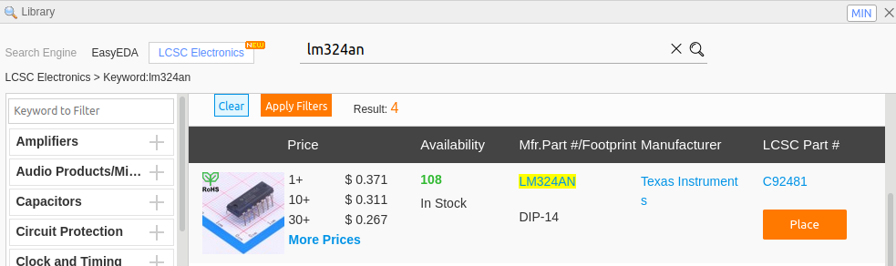
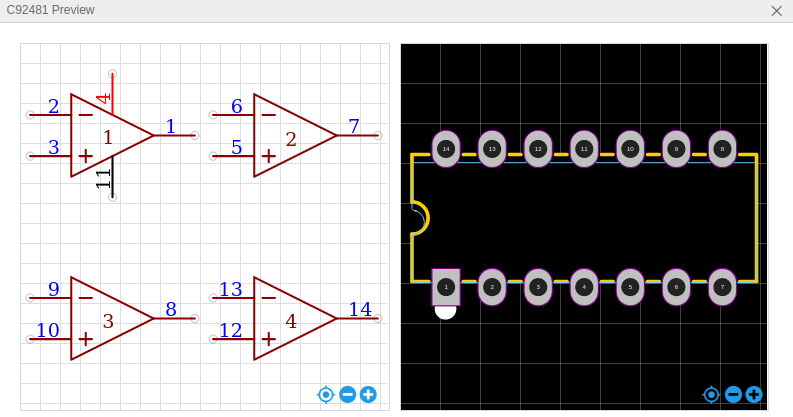
Here’s the op-amp showing both the PCB footprint and the schematic parts
Once everything is hooked you you can choose “Convert Schematic to PCB” and the website will make a first stab at a PCB
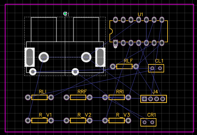
The next step will be to lay the components out more attractively so we can then route the PCB using EasyEDAs Auto-Router. Since I intend to make this PCB at home I want it to be single layer and use really fat traces. Before auto-routing, I changed Auto-Router design parameters to give me a Track Width to be 0.75mm and a Clearance of 0.35mm. I also told it to only auto route the bottom layer so I could have a single layer board.
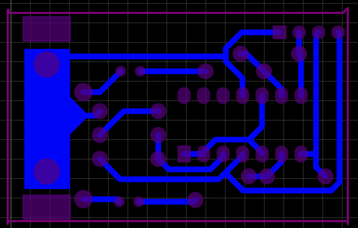
It took some manual tweaks of the component locations, but I was eventually able to get it to route a PCB with all the connections made.
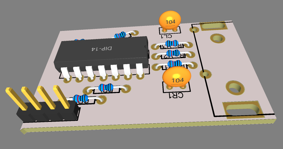
And here’s it in 3d (Note I have the right footprint for the RCA phono jacks but there’s no 3d model for that part)
I could have just decided to buy a nicely polished PCB from China at this point. In retrospect, it’d be well worth $11 to skip the following section!
There’s a piece of software called FlatCAM that will take the Gerber PCB files that are generated by EasyEDA and convert them into GCode that I can send to my Inventables Carvey CNC machine.
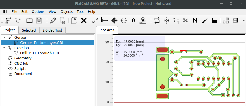
In FlatCAM, start by Opening the Gerber file called Gerber_BottomLayer.GBL and the Excellon File Drill_PTH_Through.DRL. Both of these should be in the fabrication zip file from EasyEDA.
Next use the Tool > 2-Sided PCB tool to mirror both of these layers. Since we’re only making the bottom layer, but we’ll be carving and drilling from the other side, we’ll need to that.
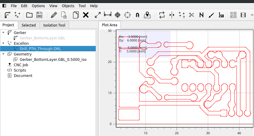
That file can then be saved as a gcode file for carving.
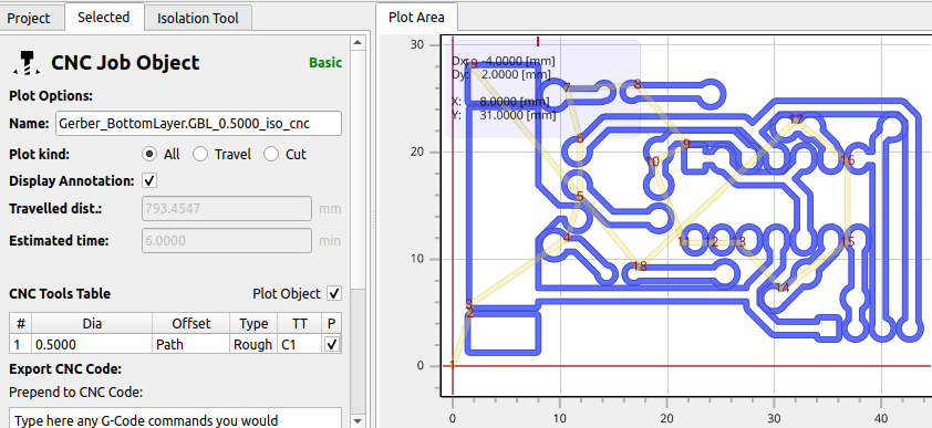
Now we can move onto the drill holes. I bought a set of PCB Hole Drills which match the sizes that my design calls for. If I go back and select the Excellon file that I imported earlier, I can now see the drill bit sizes:
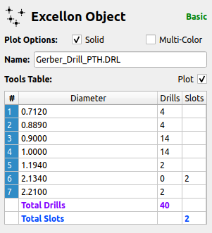
I can select these one at a time and create a CNC job object for each one. I named them based on the color of the Inventables drillbit so it’d be easier to manage when I actually machined them.
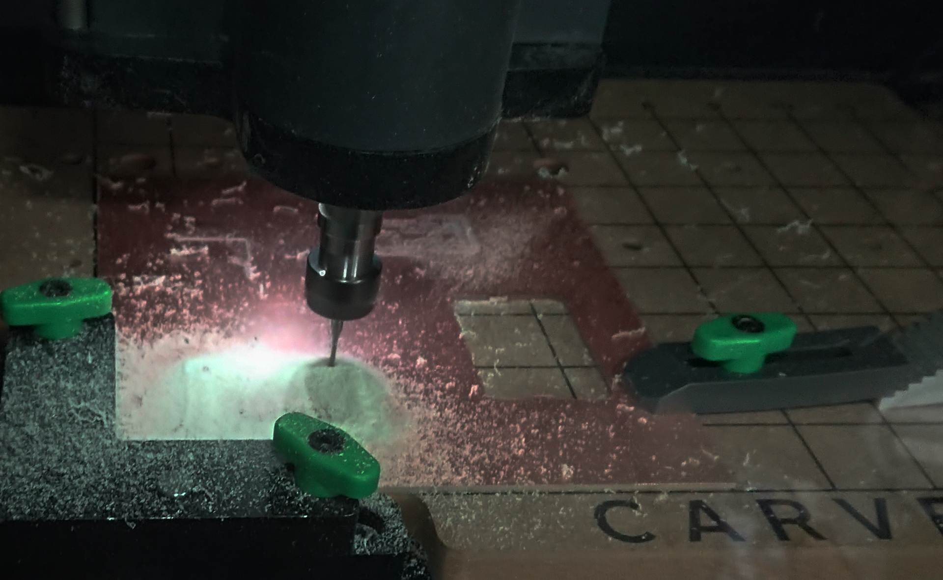
Finally i’m ready to actually import all the files into Easel and carve the PCB. I had to tweak the depth of the isolation layer carve to get a smooth result, but in the end it worked quite well.
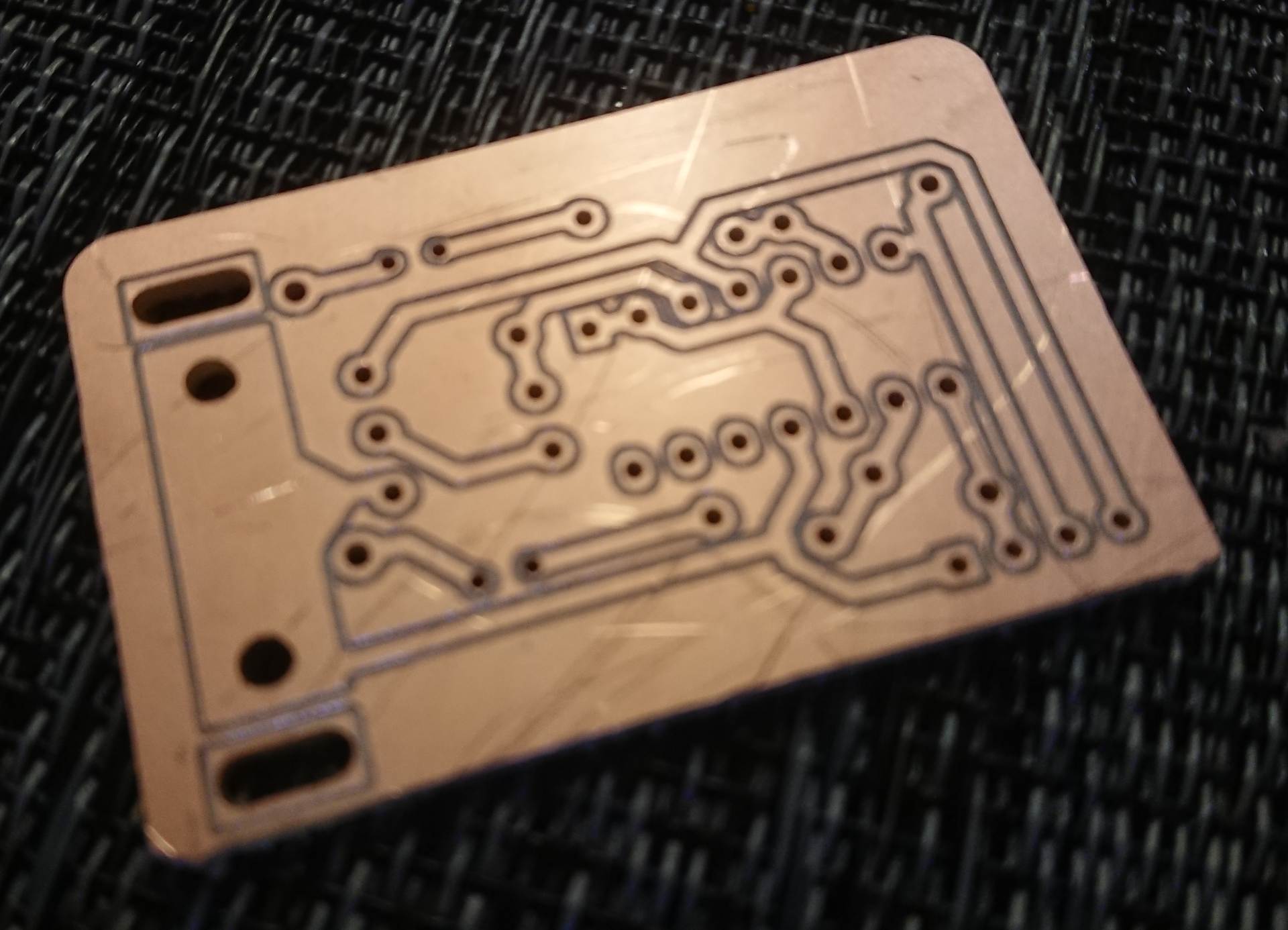
It was quite hard to actually solder the components to the board as I’m used to working with PCBs that have a professional solder mask applied. It’s also surprisingly hard to get all the components in the right holes without having a silk screen mask.
Here’s the finished product, hooked up to an ESP32
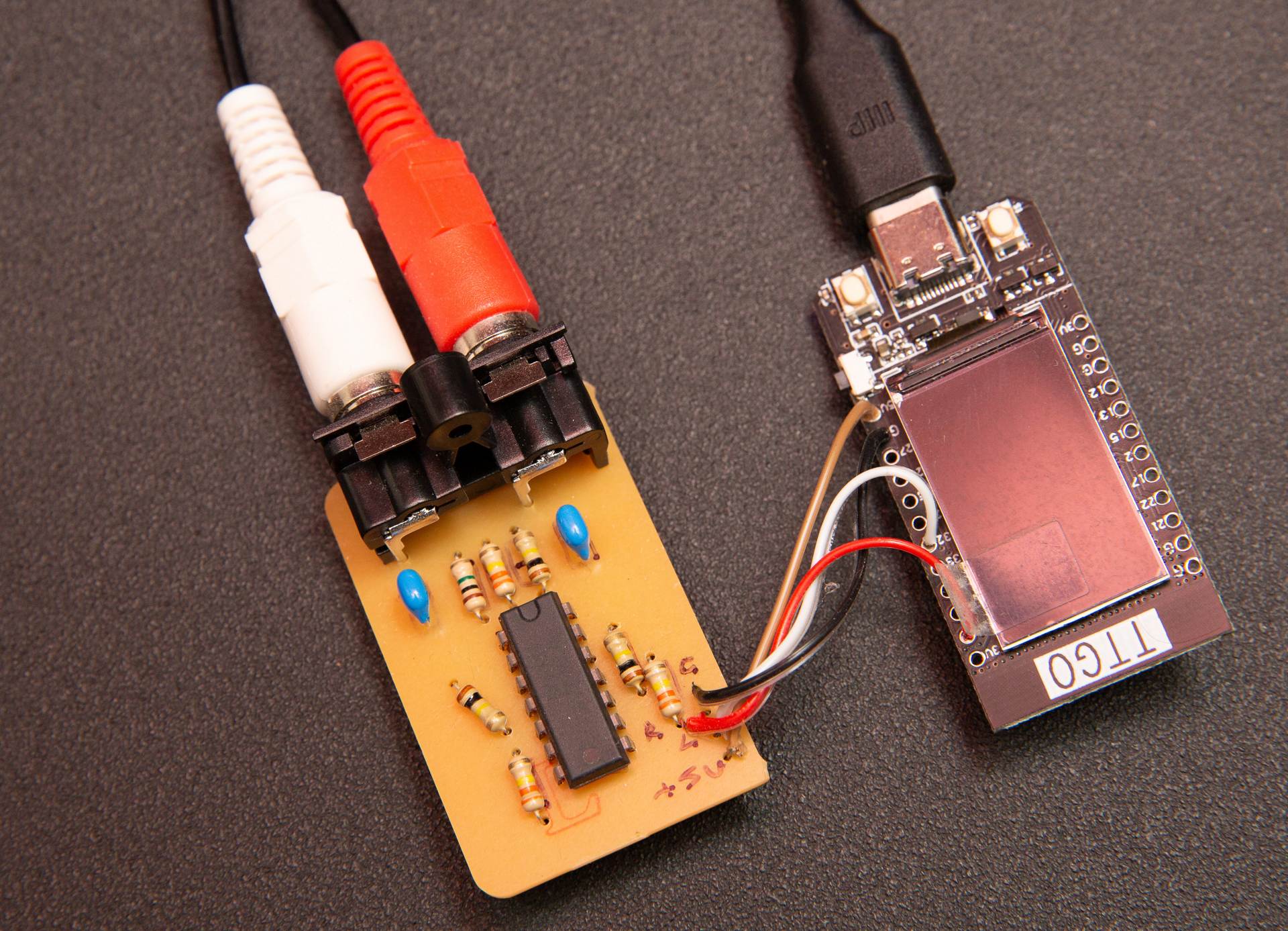
I really should have put a low-pass filter in here, ultimately i’m sampling at about 32kHz and will probably be introducing some aliasing problems. I don’t think it matters too much for my particular application, but it’s something to think about i you really want to record audio with a circuit like this.
Introduction Running various services at home can be a great convenience, but it’s incredibly frustrating when the network goes down and you’re not there to restart everything. I’ve …
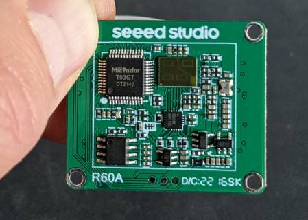
Introduction I recently bought a tiny 60GHz radar module to use in a project. This is a really neat little board that claims to be able to read breathing and heart rate data from a subject with 90% …
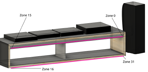
Introduction I’ve previously discussed building a Stereo Console that is backlit using a LIFX Z-Strip. We thought it’d be cool if the backlight modulated in conjunction with the music we …