B2 Processing/Max/Syphon/Resolume Demo
Introduction I recently had the chance to build something in the Atlas B2, a cool space that has multiple projectors, mocap, lights, and 40-speaker surround sound. I’d done a number of cool …
Shaders are a powerful way to apply powerful logic to the individual pixels in a p5 sketch. We write them in the GLSL language (a form of C) then they are compiled and (generally) run on your graphics card. They are much faster than the same operation written in pure Javascript.
My laptop has 16 CPU cores (and a javascript process typically only uses 1); however, it has 6,144 GPU shader cores, and a WebGL shader can use all of them. It looks something like this video.
Here’s a diagram from the Graphics Pipeline article on Wikipedia:
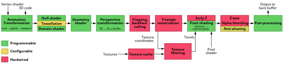
This summary will focus on only the “Pixel shading” portion of the pipeline as used in WebGL shaders; it is possible to use “Vertex Shaders” too, but I’ve found those to be of relatively limited use when post-processing a p5 sketch.
We’ll use the WEBGL canvas in P5 to render the viewport. We typically use WEBGL for 3D - to make it work for 2D graphics, we’ll make a straightforward 3D scene.
  createCanvas(400,400, WEBGL);
  noStroke();
  rect(0, 0, width, height);
Our shader consists of two separate files, a .vert file and a .frag file.
Here’s a boilerplate vertex shader. You can pretty much use this version of shader.vert for everything else we’re about to do.
// our vertex data (set by p5)
// this will be in the World Coordinate space
attribute vec3 aPosition;

// our texture coorinates (set by p5)
// These will go from 0 to 1
attribute vec2 aTexCoord;

// The varying qualifier identifies this as something that will
// be passed down the pipeline to the fragment shader
//
// It's useful to have the texture coordinates from 0-1 so we
// copy them into this varying field
varying vec2 vTexCoord;

void main() {

  // copy the texture coordinates
  vTexCoord = aTexCoord;

  // copy the position data into a vec4, using 1.0 as the w component
  vec4 positionVec4 = vec4(aPosition, 1.0);

  // Our scale is from 0-1, but we want to make it look like it's
  // from -1 to 1 since that's going to look the same as the p5
  // layout
  positionVec4.xy = positionVec4.xy * 2.0 - 1.0;

  // send the vertex information on to the fragment shader
  gl_Position = positionVec4;
}
Now let’s create a fragment or pixel shader in a file called shader.frag.
// this is required
#ifdef GL_ES
precision mediump float;
#endif

// varying to receive the UV coordinates from the vertex shader
varying vec2 vTexCoord;

// function to calculate the color of the pixel
void main() {
  gl_FragColor = vec4(vTexCoord.x,0.0,0.0,1.0); // R,G,B,A
}
Finally we can set this up in our sketch.js file
let theShader;

function preload()
{
  theShader = loadShader('shader.vert', 'shader.frag');
}

function draw() {
  // shader() sets the active shader with our shader
  shader(theShader);

  // we draw our 2d drawing onto the plane
  rect(0, 0, width, height);
}
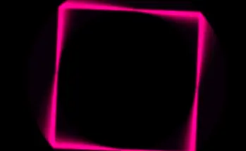
Here’s what we get:
0.0 but not just 0We can pass values into the shader as a “uniform”. This is one value that gets shared between all the shaders cores processing each frame of the drawing. Useful things to pass in might be:
  theShader.setUniform("uResolution", [width, height]);
  theShader.setUniform("uMouse", [mouseX,mouseY]);
  theShader.setUniform("uMillis", millis());
Now we can change our shader to vary the color based on the mouse position:
void main() {

  // convert the mouse position into the same coordinate space
  // by dividing by resolution - then flipping the y coordinate
  vec2 mouseTransformed = uMouse / uResolution;
  mouseTransformed.y = 1.0-mouseTransformed.y;


  // calculate the distance from the mouse to the pixel
  float distToMouse = length(vTexCoord - mouseTransformed);

  // render a color based on this distance
  gl_FragColor = vec4(1.0-distToMouse,0.0,0.0,1.0); // R,G,B,A
}
Everything on shadertoy.com uses this approach; there are a lot of really good samples here which create all kinds of shapes and forms by varying the color of the pixels without having any true 3d objects behind them. (Shadertoy uses GLSL ES 3.0, so not everything there can easily be ported to p5)
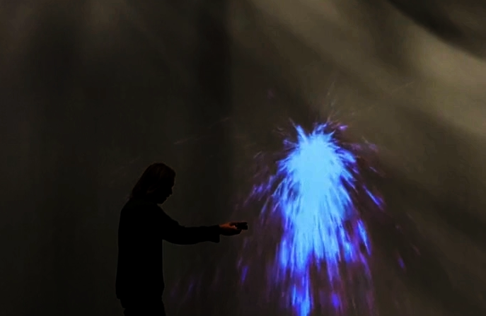
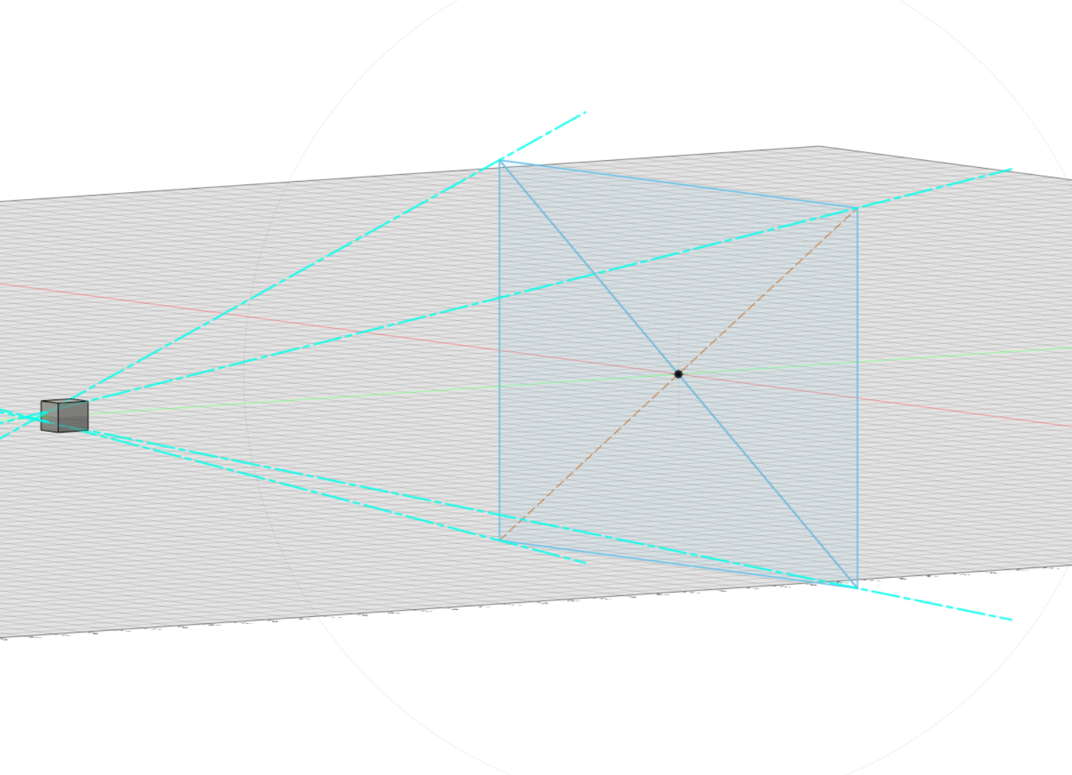
I built my project for the Clock Assignment by marching a ray from the Camera position through the pixel we’re interested in on the screen and then used a sliding noise texture to decide if I’d hit a snowflake.
<high school geometry>You can use the vector-dot-product to test which side of a plane a particular point is on. I define the light shaft as four planes and consider the flake highlighted if the dot-product of the snowflake position and each of the four planes is negative</high school geometry>
Introduction I recently had the chance to build something in the Atlas B2, a cool space that has multiple projectors, mocap, lights, and 40-speaker surround sound. I’d done a number of cool …
Introduction p5 can be used for 3D graphics, although it makes much more sense to use something like three.js if you want to do any serious 3d browser development. Where WebGL really shines in p5, in …