Introduction
I’ve previously discussed building a Stereo Console that is backlit using a LIFX Z-Strip. We thought it’d be cool if the backlight modulated in conjunction with the music we were listening to, so I built an Arduino to sample audio, perform an FFT and then produce a light pattern that roughly corresponds to the audio spectrum.
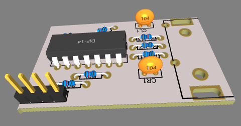
Circuit
I’ve discussed the Front-End circuit in more detail here. It is responsible for taking the audio feed in and amplifying it into a range that I can sample with an ESP32 development board.
Connection to LIFX
LIFX provide several ways to connect. Perhaps the easiest is their cloud interface, but this isn’t going to be fast enough for me to update in time with the music. Their direct UDP interface is much more lightweight and can, in theory, take as many as 20 updates per second.
The Fast Fourier Transform is the standard way for converting data from the Time Domain to the Frequency Domain. The technical details of that are well beyond what I’m going into here, but our flow is going to be
- Sample a section of audio
- Perform FFT to get a measure of how much of the signal falls into different bins
- Combine those bins into larger bands that correspond to segments on the LIFX Z-Stip
- Send that packet via UDP over WiFi to the light
- Repeat
The output of the FFT algorithm depends heavily on the specifics of the sampling rate and the buffer size. In the end, I took 1024 samples of each stereo channel at 30,720 Hz - this gives me a bin width of precisely 30 Hz (the same increment as the spectrum analyzer on my Optonica power amp.)
I define my bands at the top of the code in terms of their absolute frequencies, and then I convert those to groups of FFT output bins in the initialization code
const uint16_t SAMPLES = 1024; //This value MUST ALWAYS be a power of 2
const double SAMPLE_RATE_HZ = 30720;  // This is customized to get me a 30Khz band size!

#define NUM_BANDS  8   // The number of bands that we want to break the signal into
const int bands[NUM_BANDS] = {  120, 360, 720, 960, 2000, 4000, 8000, 15000};  // frequencies in Hz
When I convert those to bins, they don’t line up exactly with the target frequency, but it’s close enough
With a sample rate of 30720.00Hz, and a buffer size of 1024 samples, we'll have an FFT Bin Size of 30 Hz
Band 0 will run to 120 Hz vs an target of 120 Hz
Band 1 will run to 360 Hz vs an target of 360 Hz
Band 2 will run to 720 Hz vs an target of 720 Hz
Band 3 will run to 960 Hz vs an target of 960 Hz
Band 4 will run to 1980 Hz vs an target of 2000 Hz
Band 5 will run to 3990 Hz vs an target of 4000 Hz
Band 6 will run to 7980 Hz vs an target of 8000 Hz
Band 7 will run to 15000 Hz vs an target of 15000 Hz
This also means that I’ll be capturing about 33 mS of audio, performing the FFT and sending the UDP packet. I’m able to repeat that process about 12 times a second, so that does mean that ultimately i’m only sampling about a third of the total audio data. Again for my application that doesn’t seem to be a problem. (I will note that the ESP32 has two cores and could in theory be sampling with one while doing the FFT with the other, but that’s a project for another day.)
Why not 44.1kHz?
Most high-quality audio recordings are sampled at either 44.1 or 48kHz. Unfortunately, the quirks of how FFT works means it’s harder to analyze low frequencies when your sampling rate is higher (without going to a larger buffer size which slows everything down). 30720 Hz seems to be a sweet spot for this particular project, and the crispy high frequency details aren’t usually that visible in a spectrum analysis.
The sampling code
This is a pretty simple loop. We pre-compute the number of microseconds for each sampling period (33uS) and after taking each sample we simply wait in a loop until it’s time to take the next sample. We have buffers set up to receive the incoming samples realRight and realLeft and then we also use this loop to initialize a separate buffer that’s used in the FFT process.
  // We're going to read 1024 samples from each of the left and right channels
  for (i = 0; i < SAMPLES; i++)
  {
    realRight[i] = analogRead(36);  // read from GPIO 36
    realLeft[i] = analogRead(32);   // read from GPIO 32
    imaginaryRight[i] = 0;
    imaginaryLeft[i] = 0;
    while (micros() - microseconds < samplingPeriodMicroseconds) {
      // A small wait while we wait for the appropriate number of microseconds to hit or 32kHz sampling rate
      // slower Arduinos might need the sampling rate reduced
    }
    microseconds += samplingPeriodMicrosends;
  }
I use the arduinoFFT library to make short work of this part and do the following steps for each of the stereo channels
    FFT.DCRemoval(realRight, SAMPLES);
    FFT.Windowing(realRight, SAMPLES, FFT_WIN_TYP_HAMMING, FFT_FORWARD);
    FFT.Compute(realRight, imaginaryRight, SAMPLES, FFT_FORWARD);
    FFT.ComplexToMagnitude(realRight, imaginaryRight, SAMPLES);
This should be fairly self explanatory. The DC removal step seems important otherwise we get unusually high readings in the lowest frequency bin. When we’re done with those steps the magnitudes of each of the FFT bins are copied back into the first half of the realRight buffer.
Grouping into Bins
Here’s simplified code (for only a single channel) showing how I group the FFT bins into larger bans. I’ve already figured out which bin number we need to cut off at for each frequency band and stored that in the bins array.
    for (i = 1; i < (SAMPLES / 2); i++)
    {
      // Sample 0 is unusable in an FFT and only first SAMPLES/2 are usable. Each array eleement represents a frequency and its value the amplitude.
      bandTotalRight += realRight[i]; // Add up the total power in the band

      if (i == bins[band])   // if this is the last sample in the band
      {

        // Fudge the FFT levels to get a visually appealing result
        adjustedRight = bandTotalRight /8 ;

        // Fade out the prior peaks
        peakRight[band] *= 0.88;

        // Only apply our new band if it's higher than the existing (faded out value)
        if (adjustedRight>peakRight[band])
        {
            peakRight[band] = adjustedRight;
        }

        // proceed to the next band
        bandTotalRight = 0;
        band++;
      }
    }
  }
I found I could mostly create the same effect by as an analog spectrum analyzer by slowly fading out each peak (we drop it to 88% of it’s value with each 100ms cycle) and then by only including the new number if it’s higher than the previous peak.
Talking to LIFX
I couldn’t find a decent LIFX library for communicating with the Z Strip when I first started work on this, so I ended up implementing my own LifxController and LifxDevice classes (at some point I should probably make these into a final Arduino library). LIFX help a lot with their well-documented LAN Protocol.
My Controller class listens for and sends UDP broadcasts, this piece of code watches for all LIFX devices on the network and doesn’t proceed until it sees one with the name we’re looking for. This means I don’t have to worry about assigning a Static IP to the Z Strip I want to control.
  // We loop until we see a Lifx device called "Hifi"
  while (controller.getDeviceByLabel(LIFX_DEVICE_LABEL) == nullptr)
  {
    Serial.println("Waiting for device by name");
    controller.probeForDevices();
    controller.readIncomingPackets();
    for (i = 0; i < controller.getDeviceCount(); i++)
    {
      if (!controller.getDevice(i)->hasLabel)
      {
        controller.getDevice(i)->probeForConfiguration();
      }
    }
    controller.readIncomingPackets();

    Serial.print("We have detected ");
    Serial.print(controller.getDeviceCount());
    Serial.println(" devices.");

    for (i = 0; i < controller.getDeviceCount(); i++)
    {
      controller.getDevice(i)->printDetails();
      if (!controller.getDevice(i)->hasLabel)
      {
        controller.getDevice(i)->probeForConfiguration();
      }
    }
  }
The call to probeForDevices sends a LIFX GET_SERVICE broadcast, and then we listen for responses from the different devices on the network. When a device responds to us we call a probeForConfiguration message that will ask it to identify itself by name. The LifxController object handles collecting all the returned UDP messages when we call the readIncomingPackets method which we stop calling once we’re in the thick of the FFT process as it’s potentially quite slow.
Here’s the result of the initial search process on my network
15:03:36.825 -> We have detected 10 devices.
15:03:36.858 -> Device:
15:03:36.858 ->   IP      192.168.3.115
15:03:36.858 ->   Port    56700
15:03:36.858 ->   Label   gerbil house
15:03:36.858 -> Device:
15:03:36.858 ->   IP      192.168.3.120
15:03:36.858 ->   Port    56700
15:03:36.858 ->   Label   Under Cabinet 3
15:03:36.858 -> Device:
15:03:36.858 ->   IP      192.168.3.119
15:03:36.858 ->   Port    56700
15:03:36.858 ->   Label   Under Cabinet 1
15:03:36.858 -> Device:
15:03:36.891 ->   IP      192.168.3.114
15:03:36.891 ->   Port    56700
15:03:36.891 ->   Label   Hovercraft
15:03:36.891 -> Device:
15:03:36.891 ->   IP      192.168.3.109
15:03:36.891 ->   Port    56700
15:03:36.891 ->   Label   Graham Bedside
15:03:36.891 -> Device:
15:03:36.891 ->   IP      192.168.3.112
15:03:36.891 ->   Port    56700
15:03:36.891 ->   Label   Frances Bedside
15:03:36.891 -> Device:
15:03:36.891 ->   IP      192.168.3.108
15:03:36.891 ->   Port    56700
15:03:36.891 ->   Label   chair reading light
15:03:36.891 -> Device:
15:03:36.891 ->   IP      192.168.3.193
15:03:36.891 ->   Port    56700
15:03:36.891 ->   Label   Hearth
15:03:36.891 -> Device:
15:03:36.891 ->   IP      192.168.3.118
15:03:36.891 ->   Port    56700
15:03:36.891 ->   Label   Under Cabinet 2
15:03:36.891 -> Device:
15:03:36.891 ->   IP      192.168.3.189
15:03:36.891 ->   Port    56700
15:03:36.891 ->   Label   Hifi
Once we’ve found the device we’re looking for, we can (if it’s a Z Strip) send it a new set of zone values with a call that passes in a pointer to an array of 82 HSV color values. This particular Z Strip only has 24 zones, but it just seemed easier to send the hypothetical max number of supported zones. This call will throw a UDP packet out onto the network and then not even care if it gets an acknowledgment back - we’ll have moved onto the next sample by that point.
hifiLightStrip->setColorZonesHSV(&(colors[0]), 82);
Mapping the bands
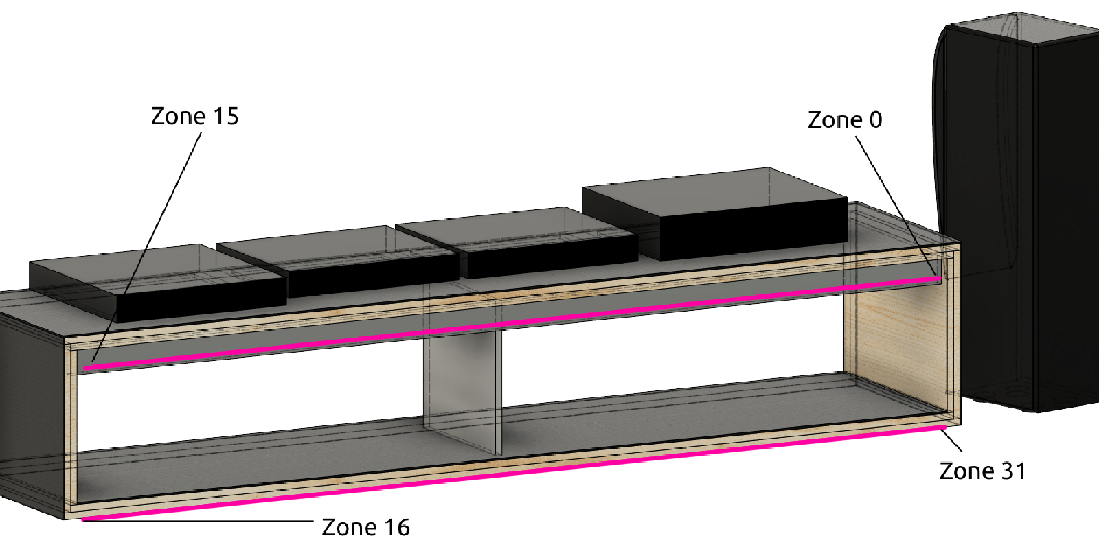
Each LIFX zone has a Hue, Saturation and Brightness (HSV) and my particular configuration has 32 zones which are wired on the back of the console like this:

I used a 3.3ft Litcessory Extension Cable to make a connection between Zone 15 and 16 and so i didn’t have to worry about trying to make a tidy LIFX corner or having lights down the side of the hifi.
Here’s the code to map the two sets of 8 bands onto the light strip zones:
  for (i = 0; i < 8; i++)
  {

    // colors 0 - 15 are on top
    //16-31 on bottom

    colors[i].brightness = peakLeft[i] + LIFX_MIN_BRIGHTNESS;
    colors[15 - i].brightness =  peakRight[i] + LIFX_MIN_BRIGHTNESS;
    colors[16 + i].brightness =  peakRight[i] + LIFX_MIN_BRIGHTNESS;
    colors[31 - i].brightness = peakLeft[i] + LIFX_MIN_BRIGHTNESS;
  }

  hifiLightStrip->setColorZonesHSV(&(colors[0]), 82);
I leave the Hue and Saturation of each zone alone, and only modulate the brightness. Each zone’s brightness can go up to 65536, and I also have a minimum brightness set so I can make the effect more subtle if necessary.
When the music stops
The code has a process that looks for periods with very little audio signal in the raw samples, and if it sees 500 “silent” periods in a row then it stops the FFT process until something more exciting happens. This helps keep down the network load and slightly reduces the ESPs power consumption. It also conveniently allows the user to change the color of the Z Strip using the LIFX app, as we’ll reprobe the device when we detect more audio.
Powering it
Our pre-amp has outlets on the back for powering other equipment. The ESPs power is fed from the pre-amp so it’ll boot up when the pre-amp turns on. I power the LIFX strip from a different outlet so we can still use it as a regular accent light when we aren’t playing music.
Final Result
The code for this project can be found on Github