
ESPHome Auto-Restart Script
Introduction Running various services at home can be a great convenience, but it’s incredibly frustrating when the network goes down and you’re not there to restart everything. I’ve …
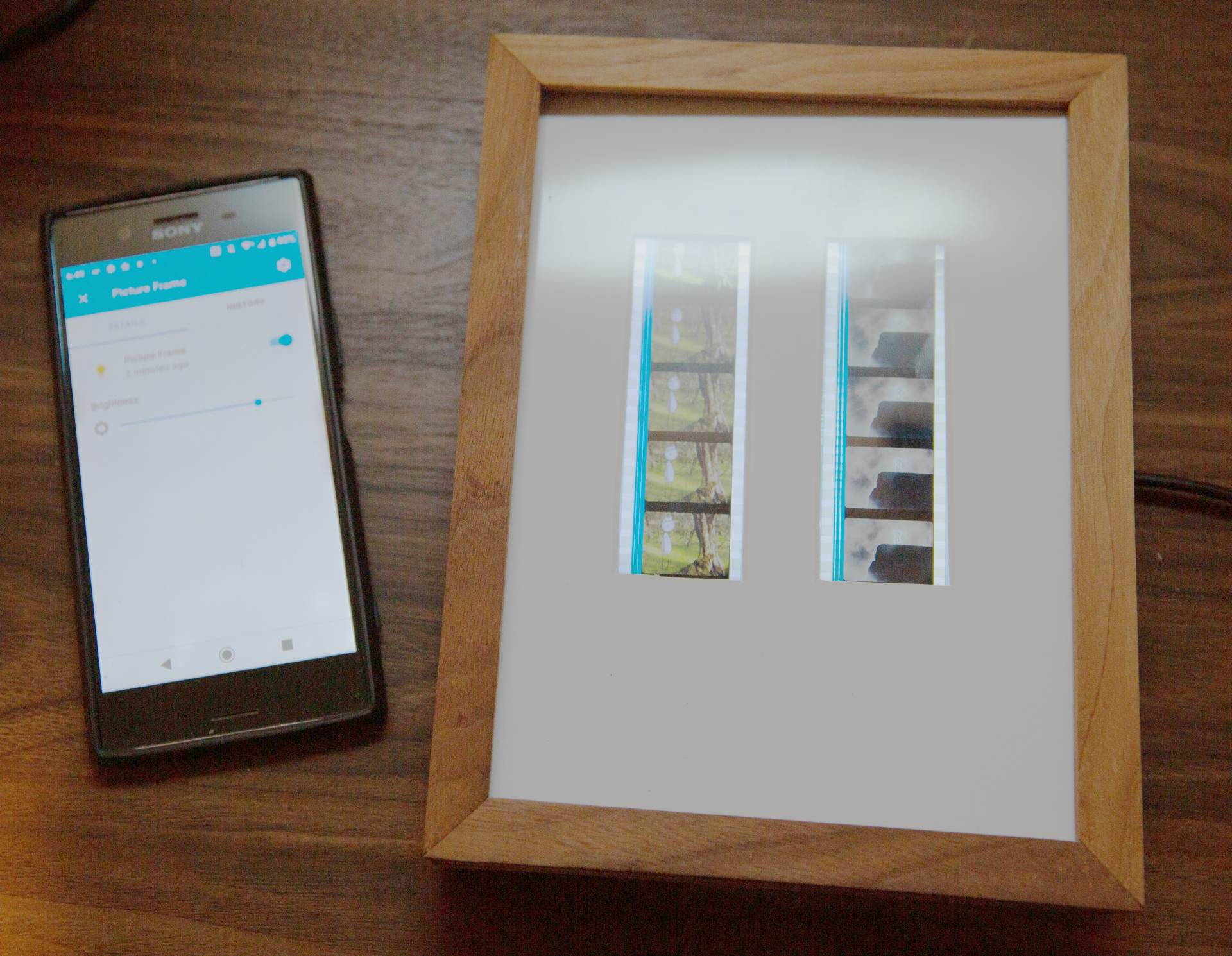
We own a couple of 5 cell pieces of an animated film and we’ve never had a good way to exhibit them, I made an illuminated frame that uses a couple of LED backlight modules. I used ESPHome to connect it to Home Assistant so it can easily be controlled like the rest of our lights.
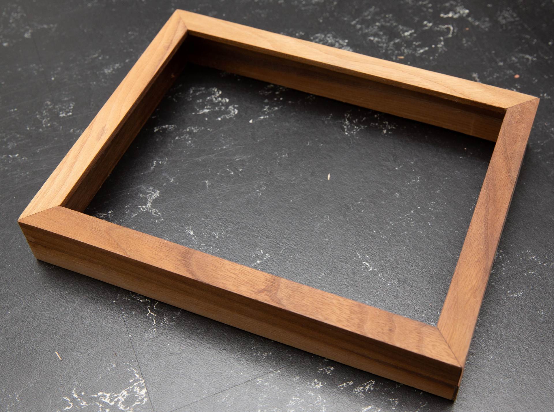
I built a custom frame out of walnut using a small CNC machine, but you could easily convert a small deep frame.
I have an Invetables Carvey and used it to make a custom frame out of 8 pieces of Walnut. The project file is here
I cut all 8 pieces, glued them together and lightly sanded and oiled the finished result.
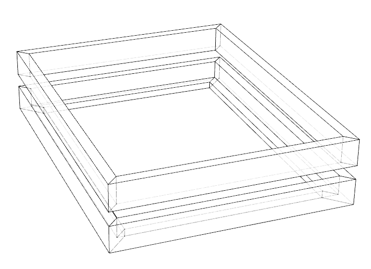
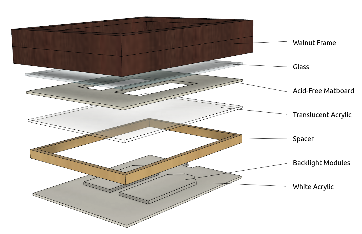
The spacer is about 0.4 inches thick - it has a few roles
The different layers are stacked like this:
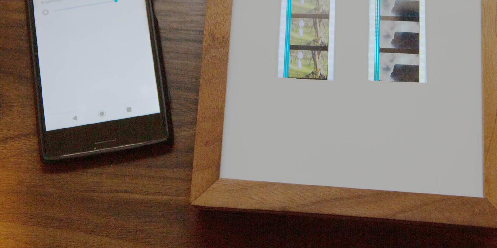
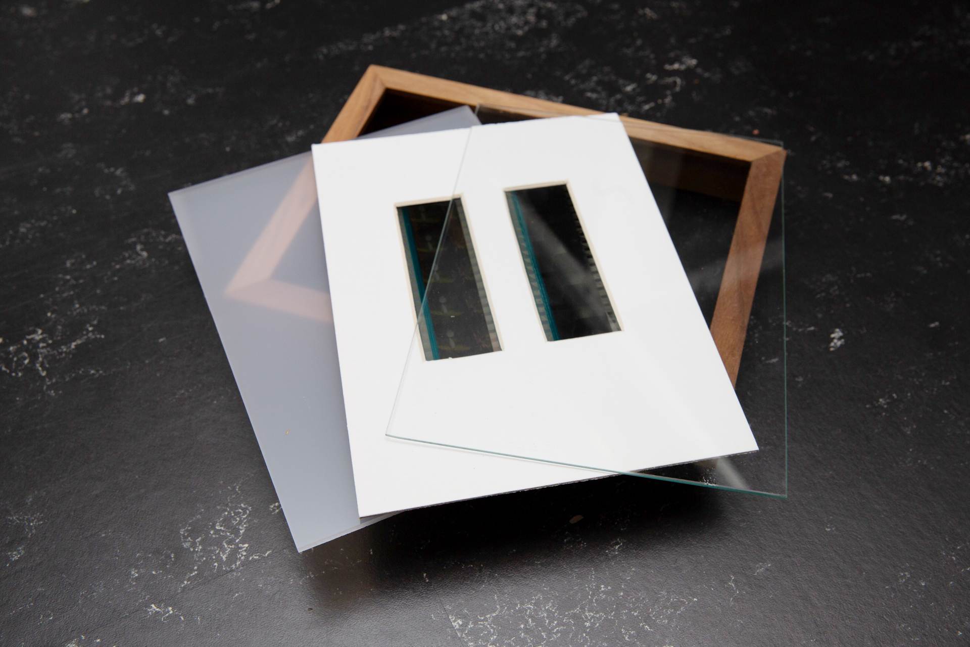
Here’s what they look like in real life
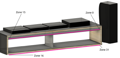
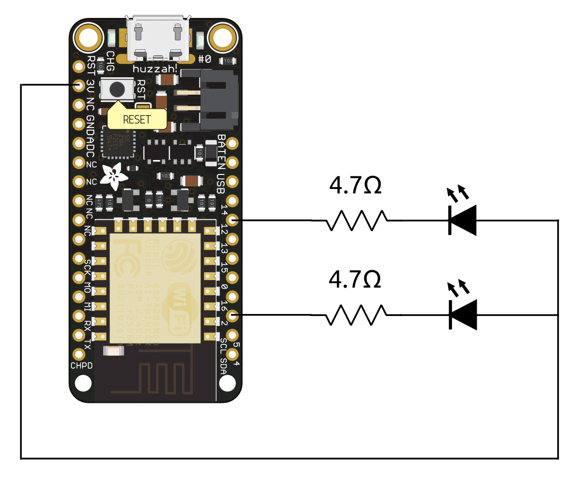
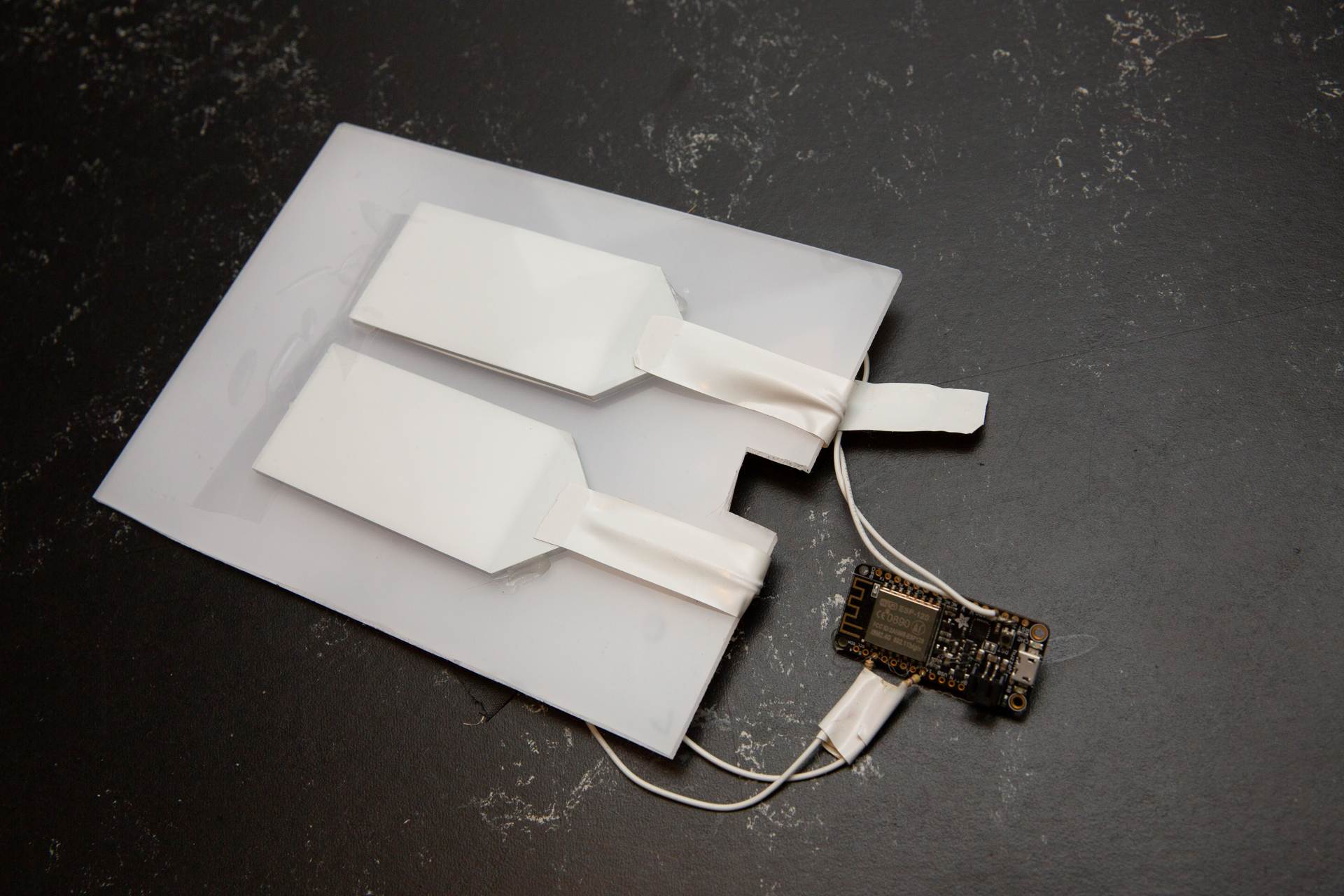
Each backlight module draws 20mA, but the maximum current that can be sourced from a single pin of the ESP8266 is only 12mA! However, according to Espressif the chip can sink 20mA. It sort of ends up looking like i’ve wired the LEDs up backwards, they draw their power from the 3.3V on board regulator and sink into two different GPIO pins, this means that the backlights will be On when the GPIO is Low, and Off when its High.
There’s a 4.7 ohm resistor in there to reduce the forward LED voltage to 3.2V.
The backlights get mounted to the opaque acrylic using a mix of hotmelt glue and tape. The ESP8266 will get glued to the back of the acrylic making it easy to plug a power cable into the back of the board.
The ESPHome project makes it super easy to connect components like this to WiFi and in turn to our Home Assistant home automation system. Here’s the YAML file for setting up this device. The simple configuration would leave each backlight individually controllable, but we don’t use it like that so I use an ESPHome template to map the two GPIO pins into a single “light”.
esphome:
  name: picture-frame
  platform: ESP8266
  board: huzzah

wifi:
  ssid: !secret wifi_ssd
  password: !secret wifi_pw

# Enable Home Assistant API
api:
  password: "xxxxx"

ota:
  password: "xxxxx"

light:
  - platform: monochromatic   # This makes a dimmable single-color light
    name: "Picture Frame"     # The name that it'll show up with in Home Assistant
    output: outputsplit       # We need to split the signal and drive each backlight GPIO pin at the same time

output:
  - platform: template        # This template splits the incoming brightness and sends it to both GPIO pins
    id: outputsplit
    type: float
    write_action:
      - output.set_level:
          id: output1
          level: !lambda return state;
      - output.set_level:
          id: output2
          level: !lambda return state;

  - platform: esp8266_pwm
    id: output1
    pin: GPIO12
    inverted: true          # We need to invert the output signal because we're sinking the LED current
  - platform: esp8266_pwm
    id: output2
    pin: GPIO2
    inverted: true
The final assembly just involves putting the layer sandwich together and tacking it in place with a little hot glue. We run a USB cable to the back of the frame and it can be controlled from our phones (or by yelling at Google)
Introduction Running various services at home can be a great convenience, but it’s incredibly frustrating when the network goes down and you’re not there to restart everything. I’ve …
I didn’t start out intending for this to be such a big project. It started out with an attempt to make a piece of furniture for our HiFi and ended up with a bunch of hardware and software design …
Introduction I’ve previously discussed building a Stereo Console that is backlit using a LIFX Z-Strip. We thought it’d be cool if the backlight modulated in conjunction with the music we …